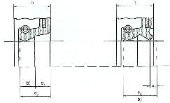
Oil seals: Installation guidelines

General guidelines:
Depending on the type, oil seals can have a smooth or groovy rubber outside diameter, as well as a metal OD. The sealing effect is accomplished through a rubber sealing lip on the inside diameter.
Installation:
The oil seal should be installed with its sealing lip facing the surface being sealed and it should remain open. It is important to avoid damage during installation, especially to the sealing lip. Prior to installation, make sure that the housing seat is clean and that the shaft and the seal itself are properly greased or lubricated. Depending on the direction of installation, it might be advisable to use a chamfer. When installing the oil seal, please make sure that any pressure exerted falls as close as possible to the outside diameter. Applying pressure on the inside diameter might permanently damage the sealing lip.
Contact surface:
The contact area between the sealing lip of the oil seal and the rotary shaft surface is the most important functional area to ensure a proper sealing effect, i.e. the surface finish of the shaft (the counterface) is vital for the sealing properties and durability of the oil seal. The counterface) should be as smoothly sanded as possible, free of any damage, such as scratches, cracks, rust or raised sections. The surface roughness of the counterface for radial shaft seals should be kept within Ra 0,2 to 0,8 µm или Rz 1 to 5 µm и Rmax of 6,3 µm. The lower values of Ra and Rz are minimum values as otherwise lubricant supply to the sealing lip will be affected. The surface hardness of the counterface should normally be at least 55 HRC, and the hardened depth should be at least 0.3 mm. Under certain conditions, e.g. where speed are low, lubrication good and contamination absent, counterfaces having lower hardness than 55 HRC might be suitable. If the counterface surface is nitrided, the gray cast iron layer must be removed.
Housing bore tolerances:
|
|
 |
||||||||||||||||||||||||||||||||||||||||||||||||||||||||||||||||||||||||||||||||||||
|
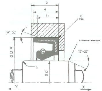
Counterfaces for standard
radial shaft seals (in mm)
|
Chamfer (in mm)
*If a shaft lead-in chamfer radius is used, it should not be smaller than the difference in diameters (d1 - d2).The radius for a seal without a dust lip (type A) is 0.6 mm, and the radius for a seal with a dust lip is 1 mm. |
||||||||||||||||||||||||||||||||||||||||||||||||||||||||||||||||||||||||||||||||||||
| About us | O-rings | Oil seals | UN seals | Wipers| Other products | Contact|
© 2004-2013 Satellite Nikis. All rights reserved. Last change on March 26, 2013 by RS